Entropy Reduction
Personal log of yet another digital native.
Project maintained by andre-abadi Hosted on GitHub Pages — Theme by mattgraham
Purpose
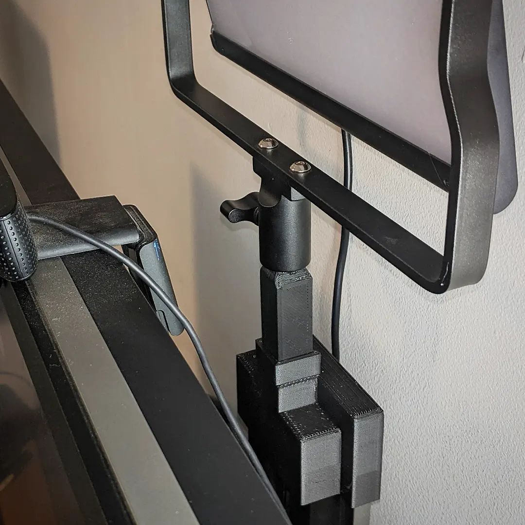
- Mount a Neewer NL660 behind a Dell U3011
References
Design Files
Actions
- Calipered (measured) rear of monitor arm
- Added 0.5mm to each outside dimension for fit
- Measured internal diameter of light pole mount, subtracted 0.5mm
- v1
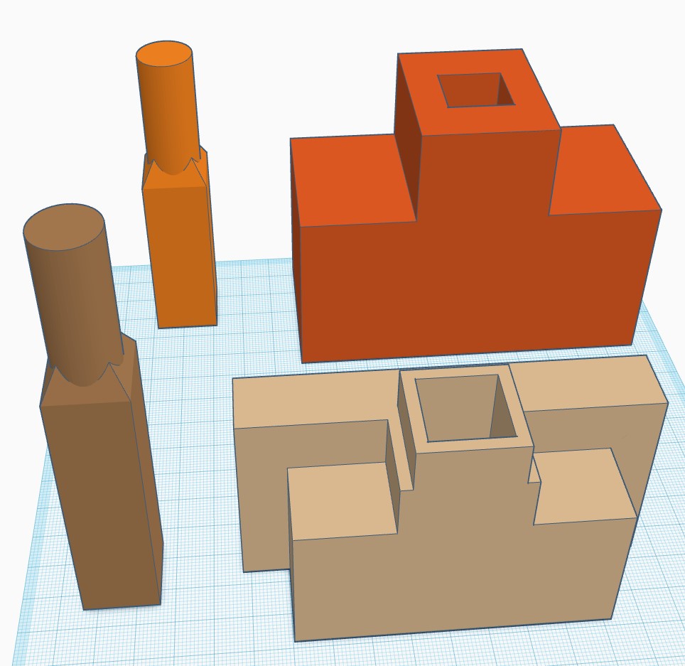
- Generated negative volumes in TinkerCAD to represent the monitor arm
- Covered in a large rectangular prism
- Designated this the base of the two parts
- Added holed-cube for placement of pole part
- Printed the base with
- 4mm nozzle
- 0.3mm layer height
- 20% gyroid infill
- Printed on longest side
- Added internal support enforcers
- 4 vertical walls
- Left print overnight (~5hrs print time)
- Had a hard time removing supports
- Base
- Fitted perfectly
- Quite heavy
- Pole location meant when light is tilted it touched the wall
- Needed redesign
- v2
- Back to TinkerCAD
- Reduced all walls of base to 3mm width
- Moved pole socket to front
- Intersected base of pole socket with top of monitor arm negative space to make an orifice (save some filament)
- Printed
- 0.6mm nozzle
- 0.4mm layer height
- 4 vertical walls
- 20% gyroid infill
- Base V2
- Fitted perfectly as last time
- Had the pole socket lower by 7mm
- Plenty strong enough
- Pole V1
- Loose fit to base v1
- Good enough fit to base v2
- Adjusted pole height for pole socket offset as a result of base V2 changes
- Adjusted pole square base to same dimensions as pole socket
- Reprinted pole
- 0.6mm nozzle warped edges a bit
- Reprinted pole didn’t fit in base v2 due to being too big
- Reverted pole v2 to same square end dimensions as v1, which had fitted fine
- Reprinted
- It worked
Reflections
- 3mm thick walls is sufficient for strong PLA parts
- 5mm thick walls results in a lot of infill, adds a lot of time, and doesn’t seem to add much strength, or at least isn’t worth the extra strength
- Internal supports are a pain to get out because removal meant pulling the rectilinear parts which didn’t in turn pull off the interface layers very neatly
- It was overkill to initially print v1 on its widest side as v2 printed upside down was strong enough not to break
Pictures